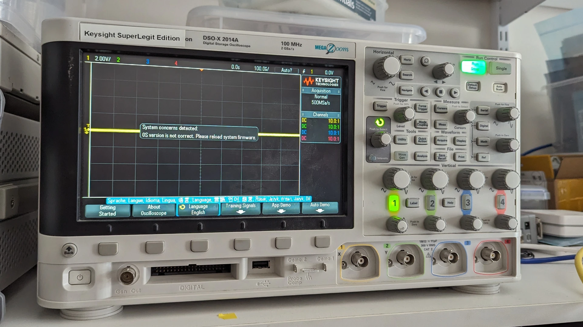
tl;dr: Agilent/Keysight DSO-X 2000 and 3000-series oscilloscopes have a fatal flaw in their PSUs. This post outline the flaw and an option for replacement.
My parents (very generously) brought me an Agilent DSO-X 2014A when I was still in undergraduate engineering. It’s been an invaluable tool for a number of projects1, and while now surpassed by many budget/cheaper models it remains a dependable tool with great performance. Years passed and my dad eventually rescued a DSO-X 3000-series from the dumpster, diagnosed the fault (not powering on) and told me about an issue with the power supplies (PSU) used in these scopes, documented in a few places:
- https://www.eevblog.com/forum/repair/agilent-keysight-3034a-x-series-oscilloscope-repair/
- https://www.eevblog.com/forum/repair/resistor-of-a-keysight-ps-doubt!/
- https://www.eevblog.com/forum/repair/keysight-dso-x-2004a-dead/
- https://www.eevblog.com/forum/repair/dso-x-3024a-power-supply-defect/ (probably the most through thread)
- https://www.badcaps.net/forum/troubleshooting-hardware-devices-and-electronics-theory/troubleshooting-game-consoles-other-weird-devices/86804-agilent-dso-x-2012a-no-power-repair
- https://www.youtube.com/watch?v=fd1uQpH9Paw (with a corresponding forum post)
See the scopes are designed to never actually turn off. Actually that a bit of a lie and it implies there’s a good reason for the choice, perhaps it’s better said that Agilent/Keysight in their infinite wisdom just made the nice clunky power switch on the front not actually switch the power off. Instead the PSU has a remote on feature and when a pin is shorted to ground then 12 V2 is sent to the scope and the magic happens. This means there’s always some quiescent power draw and the PSU is working so long as AC power is connected.
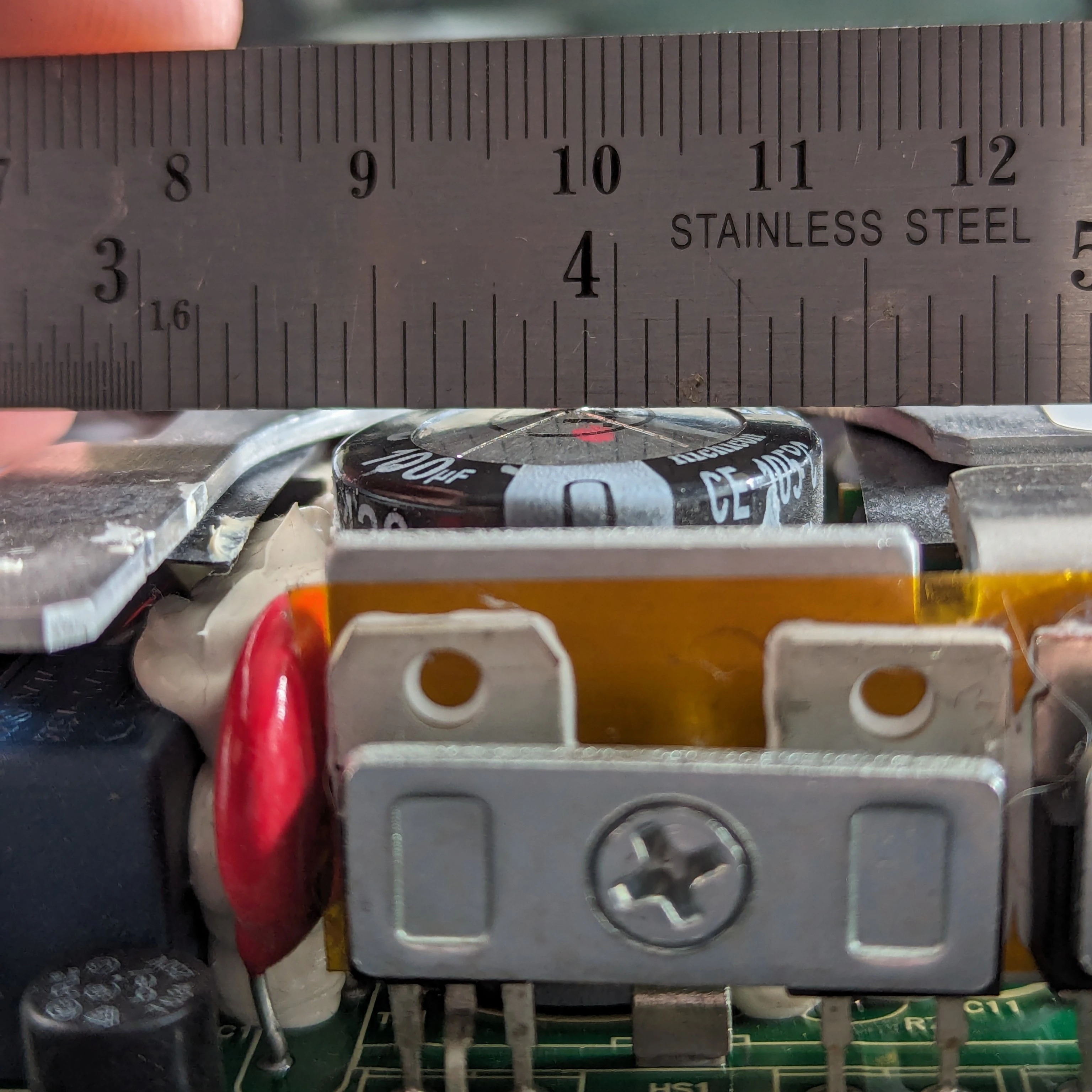
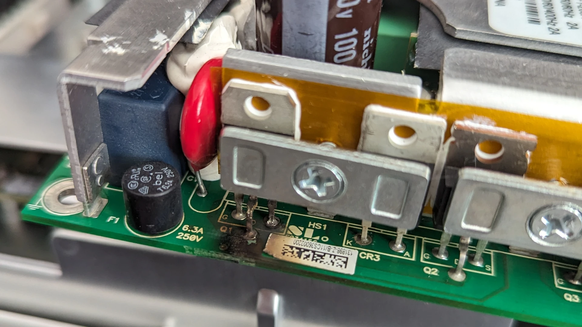
Enter the villain of the piece; 4 x 22 kΩ resistors and their close friend a 100 μF capacitor. The resistors - always being connected to power - do what they do best and turn electricity into heat. Capacitors generally disagree with heating and prematurely age when heated, losing capacitance faster than normal. The resistors are, of course, mounted directly opposite the capacitor, keeping it nice and warm… all the time. And the resistors get hot. This had killed the PSU is the 3000-series dad had rescued, and at this point I decided to just disconnect AC from my scope when not in use.
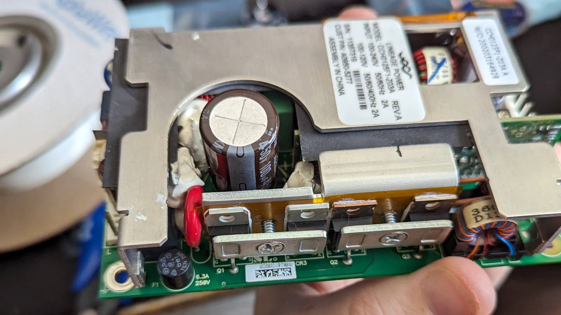
But I did eventually want to address the issue, so to fill out a DigiKey order I added a few components in and planned to replace both the capacitor and resistors. It was likely good timing too, I removed the old PSU and was greeted by a bulging capacitor and blackened area around the resistors3.
I went with these parts:
- Capacitor: Nichicon UCY2W101MHD - 100 μF 450 V 105 °C Aluminum Electrolytic Radial Capacitor
- Resistors: Vishay PR03000202202JAC00 - 22 KΩ 3 W Axial Resistors4
The repair was easy enough though some silicone has to be removed from the area around the capacitor to get it out. The new capacitor sort of floats in the large opening so maybe don’t expect a replacement like this to be mil spec. The new capacitor also stands off from the PCB a bit which may help with cooling.
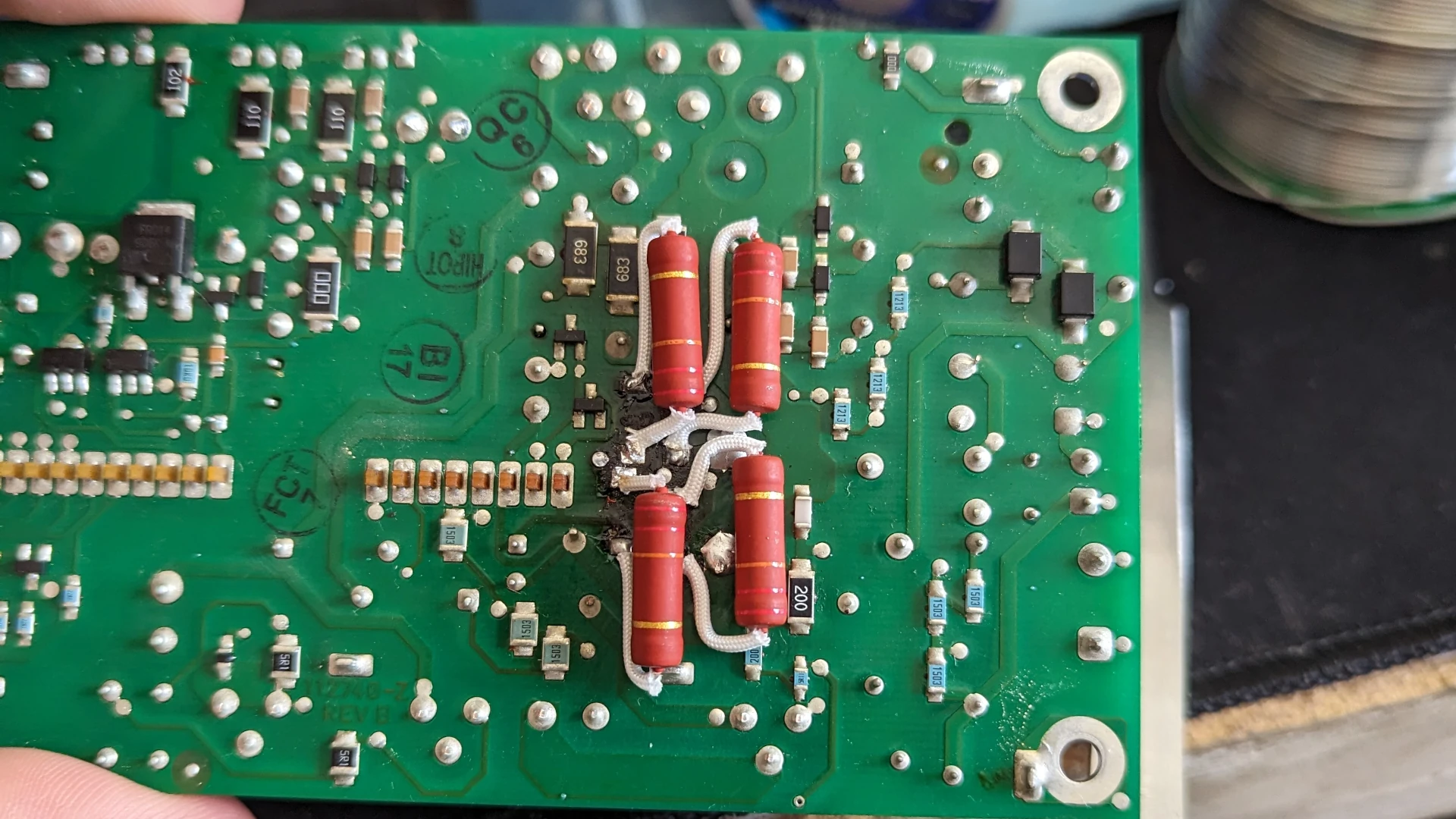
The resistors are little painful to fit, you have to really bend the leads just so to snake around everything. The PCB is also quite delicate now thanks to the hot spots, and care needs to be taken not to strip the pads. You can sort of see the blackened area near the pads. The resistor legs have some high temperature insulation over the legs and I also ended up wrapping the resistors in polyamide (better known as Kapton) tape to prevent any shorts to the PCB.
Everything went back to gether and…
Pop. Working on AC powered equipment really keeps you on your toes…
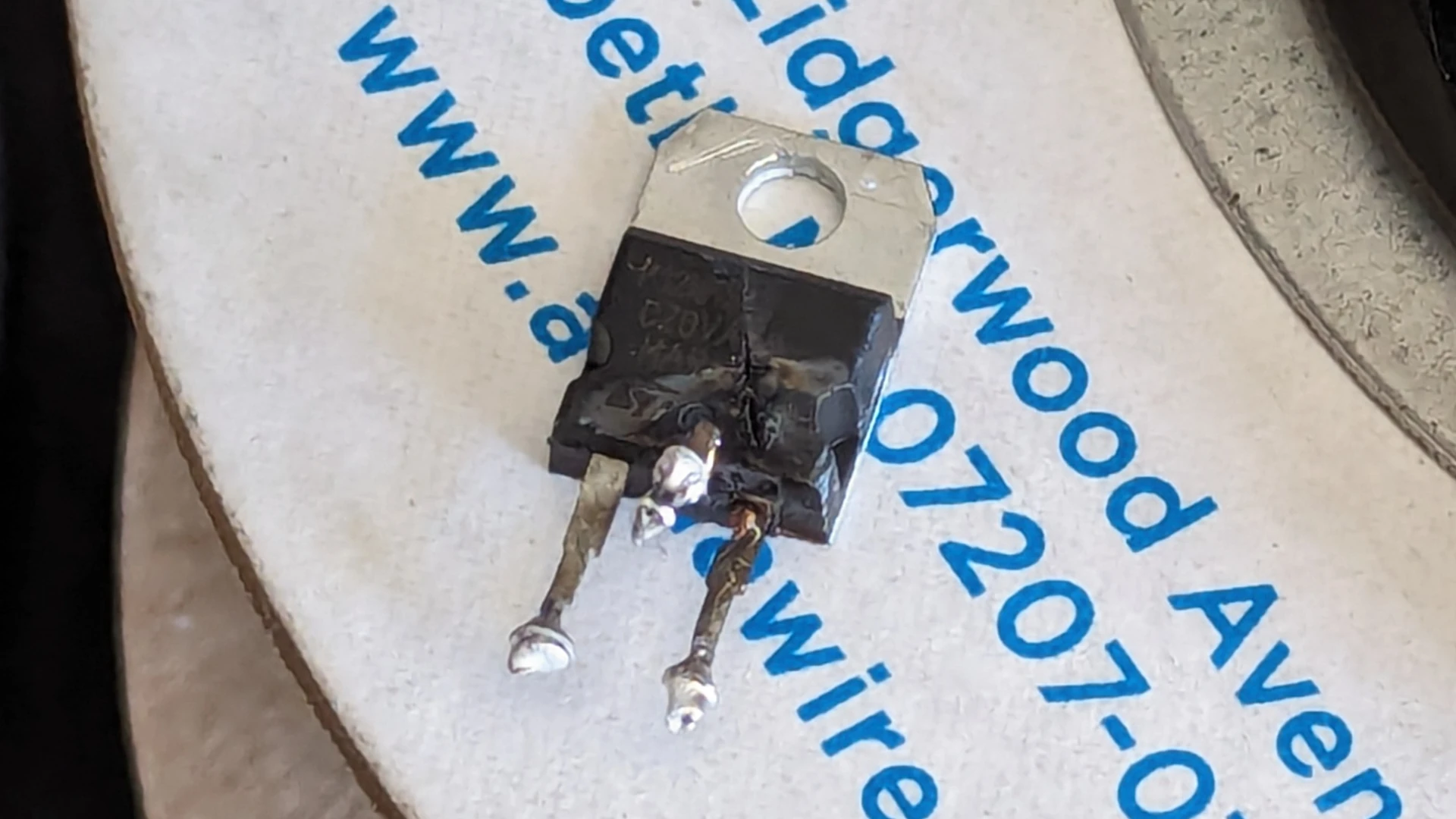
So far as I can tell I I didn’t mess anything up. My theory is that the old components were pushing the limit of operation and the FET above was exposed to its design operating voltage for the first time in ages when the other parts were replaced. After a stressful life it was too much and… well you know. The annoying thing is how catastrophic this failure was, much more in line with the results reported elsewhere. The FET is dead (duh) but on the way out it also blew the fuse F1. I had these parts available and fitting replacements left me with… a dead PSU. Nothing dramatic but also no output.
More speculation; I think the popped FET also too out the switch-mode controller on a little daughter board in the PSU. This part is basically impossible to probe, let along replace without removing the heavy heatsink5. For the record, my dad and others have made these things come back to life by replacing components, so I don’t doubt it could be done. However this is where my patience and repair efforts ended and retrofitting begins.
There are a few viable alternatives for outright replacement of the PSU, see some of the above forum threads for some ideas. I went with an RPS-160-12 which ticked most of the boxes:
I think the wattage is a little lower than the original but not meaningfully so, and unless you had a spare 400 W open-frame PSU lying around I see no reason to go down a higher-power road. The datasheet covers the connector housings and crimp pins compatible with the input, output, and signal connectors. I ended up purchasing:
- AC/DC Pins: SVH-21T-P1.1
- Signal Pins: SXH-001T-P0.6
- AC Input Housing: VHR-3N
- DC Output Housing: VHR-8N
- Signal Pins: XHP-4
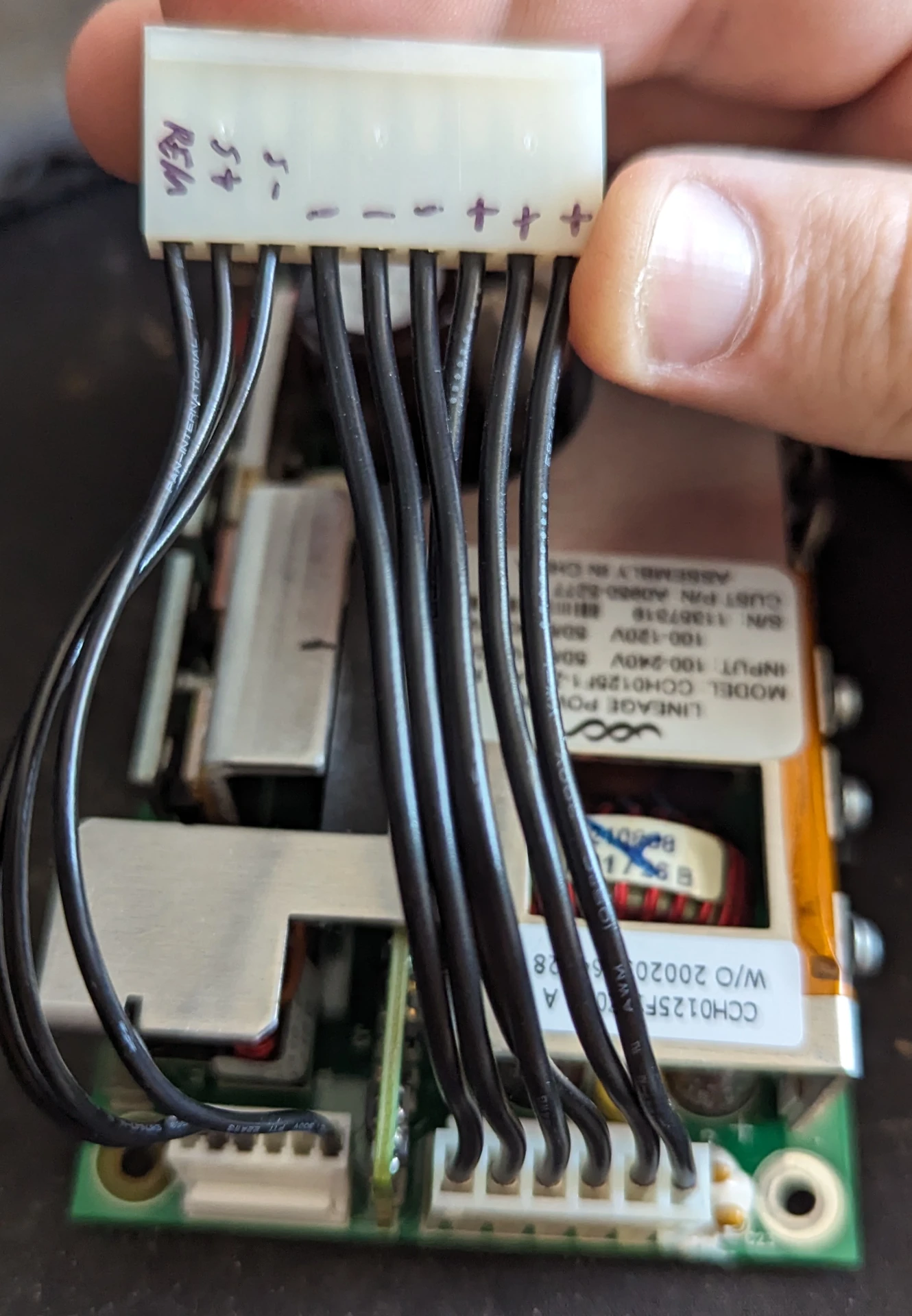
Old PSU showing pinout of the connector.
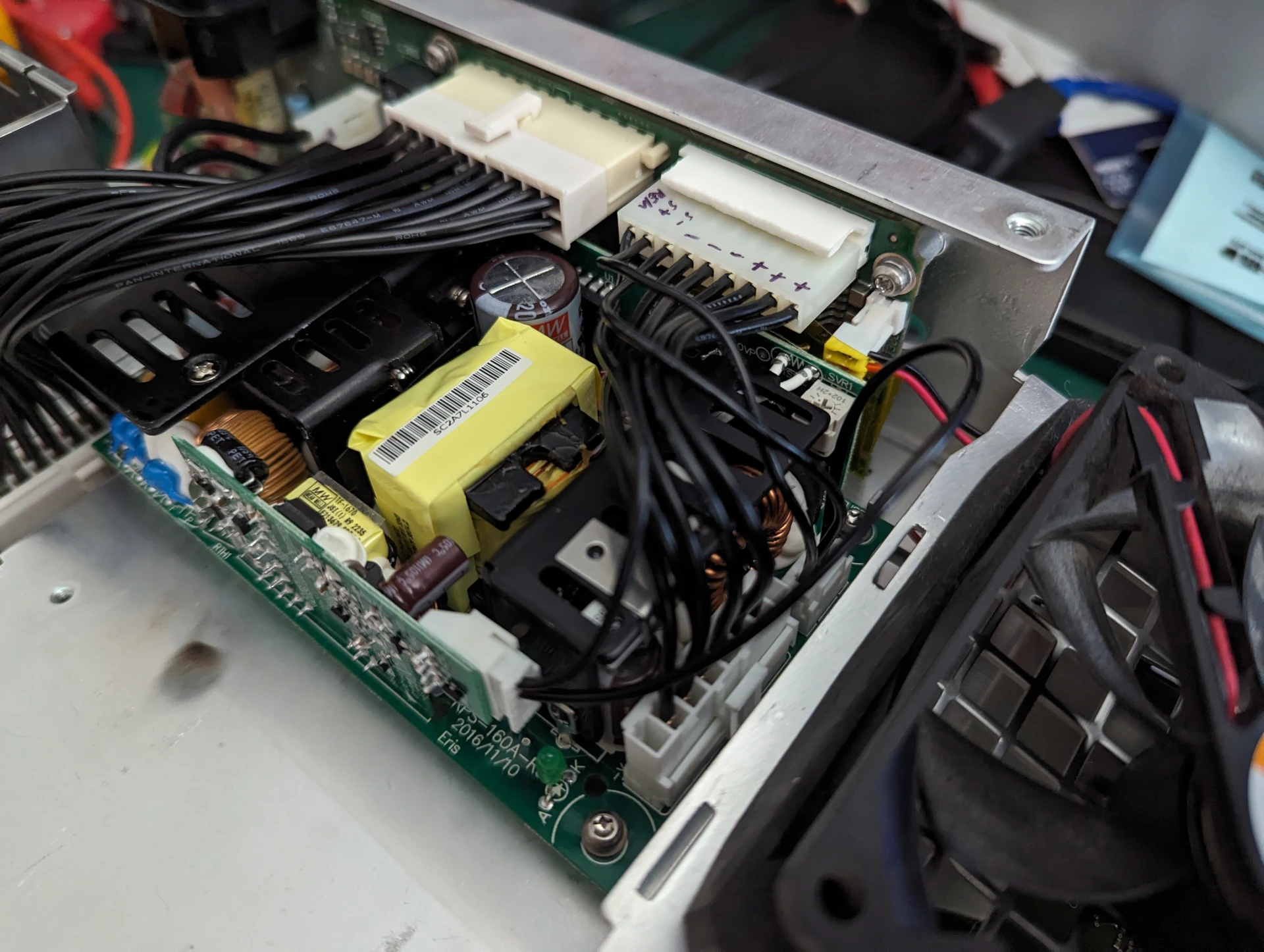
New PSU installed back into the oscilloscope.
Wiring is fairly straightforward save for one aspect. The positive and negative supply rails are wired straight over, and the sense lines go to the smaller connector off to the side. The remote pin goes to the small 4-pin connector on the vertical daughter board. Note that this connector is electrically isolated from the output, so you need to add a common connection between the ground pins on the daughter board and the supply output, I used the ground connection on the connector with the sensor pins. With this approach my power button on the front-panel works as normal; press in to turn on, some other supplies invert this.
Slightly odd behaviour, but the new supply doesn’t seem to like powering up if AC is connected with the switch already on. I initially though something was wrong because the thing wouldn’t power up, but toggling the switch made it happy 🤷.
Last thing was to adjust the output voltage up slightly to around 13 V. There is a trim-pot on the side of the PSU that can (carefully) be adjusted to increase the output. I found that until I did this there was some audible noise from somewhere inside the scope, and I had some some reports of increased signal noise7. After adjusting the voltage the audible noise went away and I haven’t seen an increase in measurement noise from a shorted probe. Mission accomplished.
On the whole I’m disappointed with the design of the original PSU. Add in the fact that Agilent/Keysight has generally been moving away from repair friendly products by not releasing technical documentation, limiting availability of replacement parts, or placing prohibitive prices on replacement parts and the whole situation stinks of planned obsolescence. If I recall correctly there have also been some firmware corruption bugs that only rear up after years of use. The DSO series oscilloscopes are great tools and it’s a shame to see the HP legacy of reliability and repairability gradually die out.
On a completely separate note I also recently put together a LAN adapter thanks to the open-hardware DSOXLAN project. Works great, highly recommend.
-
Fun fact; I did most of the PhD with data gathered from this oscilloscopes bigger cousin a DSO-X 3052. I used it to gather time-domain measurements from Surface Acoustic Wave (SAW) devices and download the waveform for analysis. Aside from the quite slow download speed… and wishing I had more than 8-bit resolution… and some VISA/SCPI quirks it was great for the job. ↩︎
-
Which I apparently didn’t take a photo of but if you find other images mine was somewhere in the middle of the road, not totally charred but much worse than some discolouration. ↩︎
-
mikeselectricstuff showed an example somewhere of using 2 x 2 0805 SMD 22 kΩ resistors in a series + parallel config to achieve higher wattage across multiple devices, I think this is a good alternative through it would still be very close to the PCB. ↩︎
-
Which, by the way, also forms part of the circuit so remember to short out the pads if ever testing without the heatsink fitted. ↩︎
-
A few commenters mention the logic of their power switches being flipped by the remote on behaviour of some PSUs. I can attest that the unit I used, in the configuration I set it up in maintains the normal operation of the power switch. ↩︎
-
More theory crafting; I suspect the scope internally regulates the 13 V down to 12 V. Feeding in 12 V makes whatever regulator they’re using for this unhappy, creating audible and electrical noise. ↩︎