tl;dr: I made an Altium script to assign functions to pins in schematic symbols based upon a CSV file. This was non-trivial.
Update: So this script has been useful to people, that’s awesome! Though I did stuff up a few things. This script cropped up on the Altium forums and a kind user also sent through some feedback via email (after some sleuthing I may have inflicted upon them to find a working email 😅). Below I say the pin designator is used for mapping, in fact it is the pin name 🤦♂️. I’ll setup a repository for the script soon™️ so updates can be centralised.
Original content follows…
Altium scripting is garbage, that’s my hot take. I’ve done a little scripting in the past usually to generate BGA pins, create footprints in bulk, things of that nature. At the time the options were JavaScript, Visual Basic script, and DelphiScript. I used JavaScript for my little utilities, which it turns out are now all broken and cause Altium to crash when run. Altium has apparently gone all in on DelphiScript - a variant of Pascal - committing to an esoteric variant of an obscure language. I assume there’s a good reason for this, there was probably an expensive license involved, better get value out of that.
I’m prefixing this post with this rant because the development and debugging experience of Altium scripting in general and using Altium as a development and debugging tool is an experience akin to pulling teeth. Of the top of my head:
- Scripts generally have to be launched from a particular context that changes the functions exposed to the script, such as with a particular document open or component selected. This means if you’re editing or debugging you have to constantly switch windows or tabs to “restart” a script. The process of running a script involves going to the File menu, selecting Run Script, selecting your script from the list of open projects (quicker) or browsing for the script in the filesystem (not quicker). Then do this a hundred times or so as you’re working.
- Debugging consists of breakpoints with optional conditions that sometimes work. Oh, and the conditions need to be in DelphiScript too. The usual stepping functions are present - and by that I mean you can continue, step in or step over (no step out) - and you get a watch window. Of course it’s up to the user to populate the watch window, it doesn’t automatically expose locals and there’s no way of even seeing the names of variables in the current scope.
- The options for exploring global context (such as the document model) are non-existent. If you can find what you’re looking for in the documentation, and it happens to have been filled out… that’s it. Be prepared to do a bunch of printing to message boxes to figure out what’s available, what types they are, and the content under various circumstances (lets ignore the error handling dumpster fire).
- There is no way to view the available properties of an object. This is beyond the pale. This aspect of the development experience caused my more headaches then anything else. There is an interactive console accessible after hitting as breakpoint, but the existential dread I felt when seeing
Objectin this view is parallel to none. It’s not clear what the object type is, what methods it has available, if it’s castable to any other type. It’s a dreadful experience. - The Altium forum requires an account for access, so it’s not indexed by any of the usual sources, and I’m curious if any of the LLMs have been trained on its contents. There’s knowledge here, but locked away behind terrible searching tools.
- There are undocumented functions, one of which we’ll be using here.
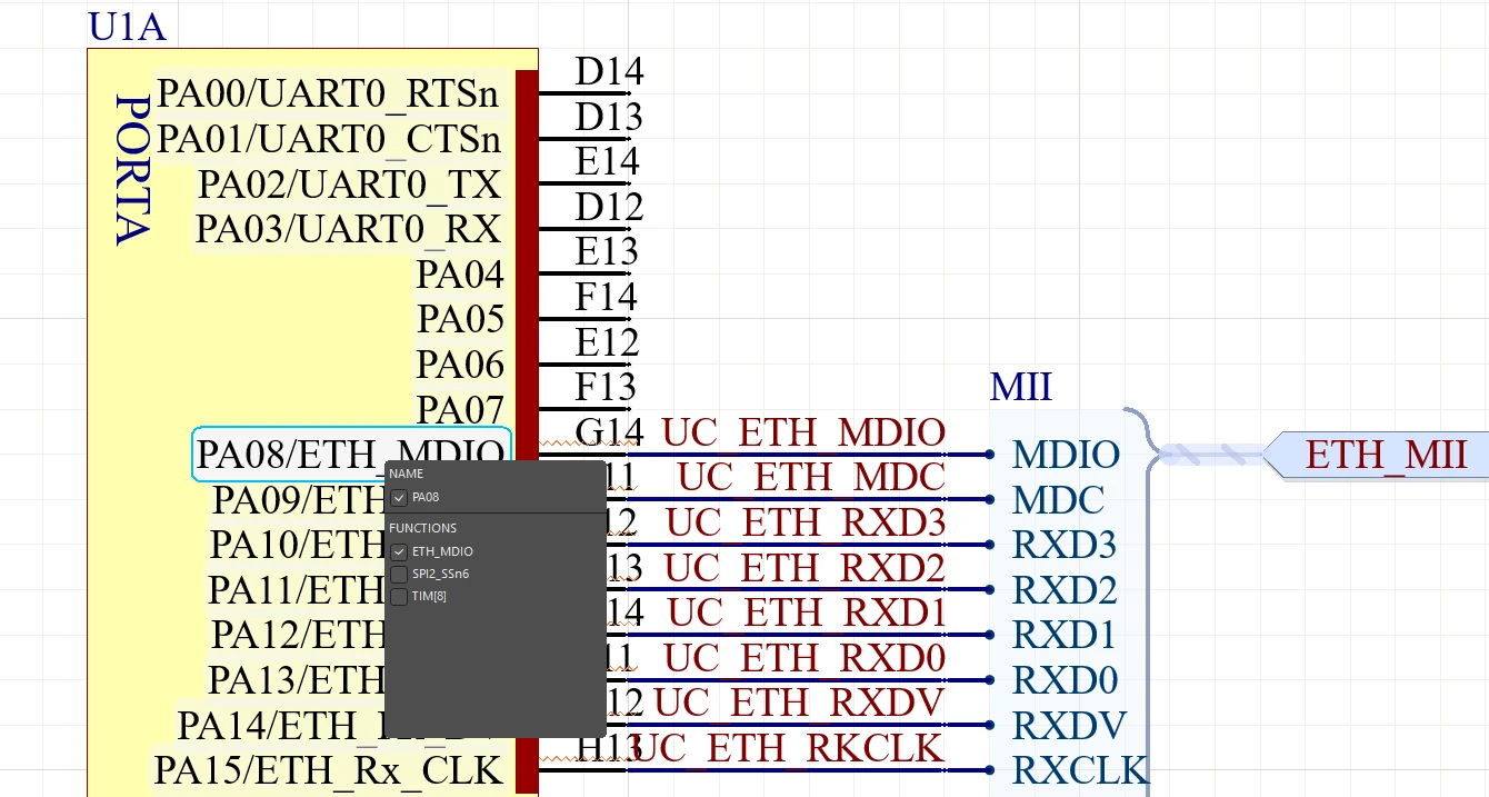
I mention all of this to put into context the decision I made. I had a footprint to make at work for a microcontroller in a BGA package with 196 pins. Take away all the functional power pins and such and there were about 105 GPIO pins configurable to 1 to 4 functions each; operating as I/O or exposing an internal peripheral. Altium recently added a feature to assign “functions” to pins, meaning in your schematic you no longer have to list GPIO4 (TC0_INT/SPI_MISO/CLK_OUT/TMS/EVERYTHING/CAKE/POTATO) you can instead show only the functions actually used by that pin, neat! The process of filling out a schematic sheet from an excel sheet after manually cleaning up tables copied from PDFs is pretty well documented - it might as well be an official procedure - so is there a way of accessing pin functions in Altium in a tabular format in the same way pin names and designators can be exposed? Nope. So, manually fill out > 100 pin functions by hand or spend a day or two (if only I’d known) figuring out Altium scripting…

Get used to errors like these.
Just a reminder that exceptions can’t be assigned to a variable in an except block in Altium’s DelphiScript, so you might know an error was thrown, but can’t see what it was!
Just an aside to mention a potential work-around. There is a thread on the EEVBlog forum that mentions this issue and proposed a workaround using the Schematic Symbol Generator tool. I didn’t go this route because I had already defined all of my schematic pins and because I’m not convinced the generaot handles BGAs with alpha-numeric designators that well.
To cut to the chase, heres the script (hosted copy):
It’s nasty and I hate it but it does function.
To use the script:
- Create a CSV file where each line is in the format:
<designator>,[function 1],[function 2],[function 3],...for as many function as desired. Each line can have a different number of functions. I manually removed empty columns generated by Excel, for example1,Function,,,to1,Function. Trailing empty fields are removed. - Run the script and select your CSV file when prompted.
That’s it. I’ve tested it all of once so YMMV but I figured this would be better shared so the next person isn’t starting from scratch.
The real guts of this come from the undocumented function SetState_FunctionsFromName. I assume this is what the schematic symbol generator uses internally, but that’s just a guess. It takes the name of a pin in the format Function 1/Function 2 and converts those to functions, that’s it. The above script basically temporarily saves the pins name, assigns it based upon the CSV line matching the designator (if found), and then restores the name afterwards.
If this is helpful, awesome. If you’re looking for a PCB tool to learn I tell my students to pick up KiCAD.